Manipulate Pixel Art With Shaders Best Pixel Art for Shaders
Constructing a Pixel Art Shader
Goal: Construct a 2d Shader that can exist used past Unity's TrailRenderer
I'd recently been wondering how to create dynamic pixel texture effects, such as beams or trails done in a pixel way. Presently afterward, I saw a mail on twitter that demonstrated a actually cool thing: a dynamically generate pixel trail behind a projectile!
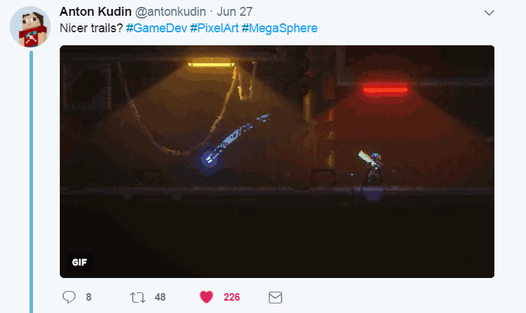
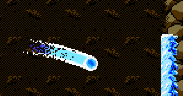
Wow! Upon request the user, he said information technology was all done with a Trail Renderer in Unity and a custom shader. This wasn't the commencement fourth dimension I'd heard of the dark magic of shaders, and so I decided to try my hand at this technique, and I came upwards with the following consequence:
Not bad! Information technology fits all the criteria I was looking for: it snaps to the pixels in the scene, it has an outer and an inner trail, and its pixels gradually become transparent. So how does it work? Read on to notice out my method for stumbling into something that looks kinda corking.
Basics of a Shader: Dissimilar Parts
So what exactly is a shader? Only, a shader is a program that alters an image by procedurally affecting the lighting, underlying colour hue, or other factors to produce a desired visual effect. The name "Shader" refers to a popular apply of introducing gradual light and shadows to simulate lite falling on the image. Since Unity treats 2nd objects every bit 3D surfaces under the hood, we'll have to go in a scrap more in depth on how they're treated in the engine. We'll talk most 2 kinds of shaders: Vertex Shaders and Fragment (or Pixel) Shaders.
The Vertex Shader performs calculations once for each vertex of the polygons we shade, and is executed earlier the fragment shader. In the vertex shader nosotros gather the information that will exist sent to the Fragment Shader which can include space relative to the photographic camera, how much fog is introduced, and the location on the texture.
Our Fragment Shader will largely intendance virtually the UVs given to it. UVs are texture coordinates that chronicle to the vertexes from which they are derived. Information technology does its calculations once (or more, for shaders with multiple passes) for each pixel.
For more caption I highly recommend visiting Michal Piatek's blog entry here:
Basic Color Shader

Alrighty, let's go ourselves a basic 1 color shader we can exercise some simple manipulation on. Here's the lawmaking for this uncomplicated shader, piece past piece.
Shader "Tutorial/SingleColor" { Backdrop { // Color property for material inspector, default to white _Color("Main Colour", Color) = (1,i,1,i) } SubShader { Tags { "Queue" = "Transparent" }
"Properties" volition define a color that we tin can change in the inspector whatever material we attach the shader to, and it will default to white. Internally we will refer to it as "_Color". Setting the render queue to Transparent will help our Trail Renderer display on summit of other objects in the scene. If y'all are using Sorting Layers, you will accept to gear up the Sorting Layer of the Trail Renderer's Renderer separately.
Laissez passer { CGPROGRAM #pragma vertex vert #pragma fragment frag #include "UnityCG.cginc" struct appdata { float4 vertex : POSITION; float2 uv : TEXCOORD0; }; struct v2f { float2 uv : TEXCOORD0; float4 vertex : SV_POSITION; };
All of our logic volition exist within the Pass scope. Showtime we define the fragment and vertex shader methods, and include the library that allows united states of america to get camera coordinates, which we'll use afterward.
The appdata struct is where we determine what information we will laissez passer to the vertex shader. Here we define "vertex" with the keyword POSITION as the vertex position in object infinite, and "uv" with the keyword TEXCOORD0 which grabs us the UV. The v2f is what will be passed from the vertex shader to the fragment shader, and nosotros'll exist passing some similar stuff, though we'll transform the object coordinates to camera coordinates with UnityObjectToClipPos(five.vertex)
v2f vert(appdata five) { v2f o; o.vertex = UnityObjectToClipPos(v.vertex); o.uv = float4(v.uv.xy, 0, 0); return o; } //externally defined colour fixed4 _Color; // pixel shader fixed4 frag(v2f i) : SV_Target { return _Color; // just return it } ENDCG } } }
Whoo, that'due south the last of information technology. Here we'll grab those camera coordinates, define the color from the inspector for use in the shader with "fixed4 _Color;", and just brand a elementary shader that but returns any color the inspector says instead of doing annihilation fancy.
Pixelization
Real quick I want to talk about my settings, and why they produce a pixelized image. All the pixelized trails you see are zoomed in on the game window, and all smoothen trails are from the scene view. My settings have a pixel as 1 unit in unity's object space, and I have non plant any shader settings that prevent this from occuring in the game view as intended. I may get back and update this subsequently if I demand to create larger pixel blocks, but for now this is what works for me.
UV colour alteration
Just, a UV is a texture coordinate. In our trail renderer, UVs will range from 1 to 0 on both the X and Y axis. The coordinate arrangement for the Trail Renderer looks like the following:
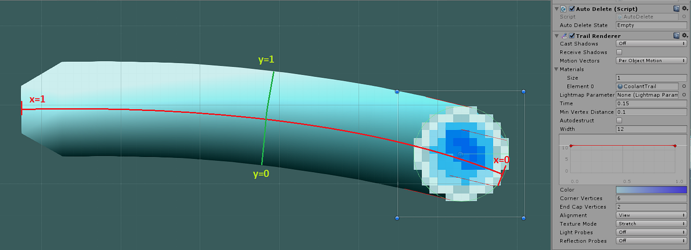
Then, the front-to-back 10 coordinate of our trail renderer texture is 0 at the front, and 1 at the dorsum. In the Trail Renderer, the full distance this covers is determined by the "Time" variable in the inspector and the objects ain movement. The y coordinate, which may announced peak-to-lesser, is in fact clockwise-to-counterclockwise, and y=0 will announced at the height instead of the lesser if the projectile is traveling to the left. Since our finish goal is symmetrical with respect to the X centrality we won't have to worry about this, but other projectiles might. The total distance the y variable covers is adamant by the "Width" variable, which tin be made to change itself over the length of the trail.
Cracking, and so let's get some cool colors in in that location! This is where the heady math (wait, delight don't leave) comes in that lets us actually determine what the final event looks like. This will exist done in the fragment shader function of the program. To start off, let's brand a gradual colour deviation betwixt the heart and extants of the Y axis. To exercise all this, we'll have to make sure nosotros're merely fading between colors for a fraction of the UV space, and and then multiply that range N by 1/N.
fixed4 frag(v2f i) : SV_Target { bladder distY = abs(i.uv.y - .5) * 2; render _Color*distY + _CenterColor*(i - distY); // just return it }

And so far and then expert. Merely nosotros should brand these two colors more distinct. Additionally, let's make the centre office fade to a darker color. We'll compress the range of the color modify even more and innovate a new color shift if nosotros're in the eye.
fixed4 frag(v2f i) : SV_Target{ bladder distY = abs(i.uv.y - .5) * 2; fixed4 c; if (distY > .7){ c = _OutsideColor; } else{ if (i.uv.x > 0.eight) c = _InsideFarColor; else if (0.eight >= i.uv.x && i.uv.x > 0.6){ c = _InsideFarColor*((i.uv.x - 0.6) * v) + _InsideNearColor*(1 - (i.uv.10 - 0.half dozen) * 5); } else{ c = _InsideNearColor; } if (distY <= .vii && distY > 0.five){ c = _OutsideColor*((distY - 0.5) * 5) + c*(1 - (distY - 0.5) * 5); } } return c; }

Alpha
We'll accept to add a bit of extra conditionals towards the pinnacle of the program to enable alpha:
SubShader { Tags { "Queue"="Transparent" } Blend SrcAlpha OneMinusSrcAlpha
Nifty! Now, what we desire is to gradually increase the rate of alpha=0 pixels towards the x=1 UV. First, we'll need a random number function for values between 0 and 1. Here's what I utilise in the instance:
bladder nrand(float2 uv) { return frac(sin(dot(uv, float2(12.9898, 78.233))) * 43758.5453); }
And when we call it, we'll pass information technology the v2f.vertex value that we set up to the photographic camera space position earlier. But wait, if we're using the photographic camera space coordinate, isn't that going to be very deterministic? Yes it will! And this means that for whatsoever given pixel in the fragment shader, there volition exist a single indicate along its path where information technology becomes transparent, giving the consequence of many particles that each fade out on their ain.
In order to make this transition faster and a bit more constrained, we're going to use a power part on uv.x rather than using the raw value. This gives us the final file:
Shader "Tutorial/Final" { Backdrop { // Color belongings for material inspector, default to white _InsideFarColor("Within Far Color", Color) = (0.2,0.2,1,1) _InsideNearColor("Inside Nearly Color", Color) = (0.5,one,i,i) _OutsideColor("Exterior Color", Colour) = (one,i,1,1) _MainTex("pixel", 2D) = "white" {} } SubShader { Tags { "Queue" = "Transparent" } Alloy SrcAlpha OneMinusSrcAlpha Pass { CGPROGRAM #pragma vertex vert #pragma fragment frag #include "UnityCG.cginc" fixed4 _OutsideColor; fixed4 _InsideFarColor; fixed4 _InsideNearColor; sampler2D _MainTex; float4 _MainTex_ST; struct appdata { float4 vertex : POSITION; float2 uv : TEXCOORD0; float4 colour : COLOR; }; struct v2f { float2 uv : TEXCOORD0; float4 vertex : SV_POSITION; float4 colour : COLOR; }; v2f vert(appdata v) { v2f o; o.vertex = UnityObjectToClipPos(5.vertex); o.uv = float4(five.uv.xy, 0, 0); o.color = float4(0, 0, v.uv.y, i); return o; } // vertex shader float nrand(float2 uv) { return frac(sin(dot(uv, float2(12.9898, 78.233))) * 43758.5453); } // pixel shader fixed4 frag(v2f i) : SV_Target { float distY = abs(i.uv.y - .five) * 2; fixed4 c; if (distY > .7) { c = _OutsideColor; if (nrand(i.vertex) > 1 - (i.uv.x * i.uv.x * i.uv.x)) c = float4(0, 0, 0, 0); } else { if (i.uv.x > 0.8) c = _InsideFarColor; else if (0.8 >= i.uv.x && i.uv.ten > 0.6) { c = _InsideFarColor*((i.uv.x - 0.6) * 5) + _InsideNearColor*(one - (i.uv.x - 0.half dozen) * five); } else { c = _InsideNearColor; } if (distY <= .seven && distY > 0.5) { c = _OutsideColor*((distY - 0.5) * 5) + c*(ane - (distY - 0.five) * five); } if (nrand(i.vertex) > 1 - (i.uv.x * i.uv.x)) c = float4(0, 0, 0, 0); } render c; } ENDCG } } }
Thanks for reading!
If you thought this was absurd, permit me know somehow, maybe I'll do more! Feedback of course is ever welcome. What was great? What was terrible?
Source: https://thedeivore.medium.com/constructing-a-pixel-art-shader-3753762f6b90
Postar um comentário for "Manipulate Pixel Art With Shaders Best Pixel Art for Shaders"